


 546 / 612

B. - Main Fuel System
On Mikuni VM - type carburetors, the pilot system and the main system
are of the independent commotion. The fuel low in these two systems is
shown in Fig.5 Bleed and primary needle jets can be used on 2 or 4
stroke, use what style achieves proper fueling for your application. It is
important to note (Fig. 5) that the main system
mixture delivery is in addition to the mixture delivered by the pilot
system. Therefore, adjustments to the pilot system should be made
irst, as they will affect the adjustments to the pilot system should be made
irst, as they will affect the adjustment of the main system to a
diminishing extent as the throttle is opened from 1/4 to full throttle.
Primary Type (Fig.6)
When the throttle valve is opened about 1/4 or more, the velocity of air
lowing through the needle jet (10) increases and also the vacuum
increases to the point where fuel can be sucked in. When the opening of
throttle valve (1) is between a quarter and three quarters, fuel passes
through the main jet (9) and, after being metered in the clearance between
the needle jet (10) and the needle (11), it is mixed with air that is metered
by the air jet (12) and atomization of the fuel is accelerated.
The mixture is then
injected, after mixing
with air lowing through
the main bore (7),
to the engine in the
optimum air-fuel ratio.
During this process of
operation, the cutaway
of the throttle valve
serves to control the
vacuum on the needle
et, thereby regulating
the amount of fuel that
is injected to the en-
gine. When the throttle
valve is opened more
than three quarters
high speed operation,
fuel is metered chiely
by the main jet (9).
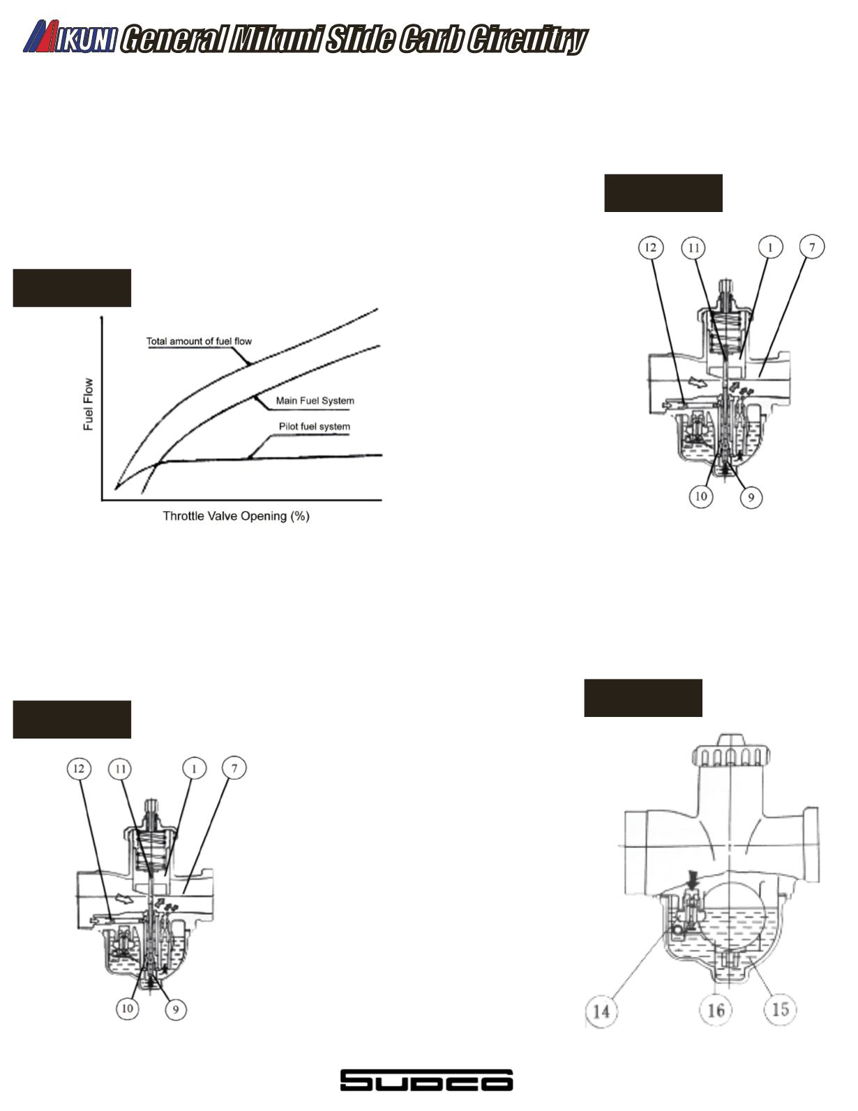
Bleed Type (Fig. 7)
The construction of the bleed - type (10) main fuel system is the
same as that of the primary type, except for the bleed holes that
are provided in the needle jets.
In the case of the primary
type, air which comes from
the main air jet is mixed
with the raw fuel after it has
been metered by needle jet
and needle. This atomiza-
tion take place behind the
nozzle screen or shroud
above the needle jet outlet.
The bleed type on the other
hand is designed to bleed
the air coming from the main
air jet into the body section
of the needle jet where it is
emulsiied with the fuel com-
ing up from the bottom.
The needle jet and needle
then meter a blend of air/fuel,
resulting in a iner atomiza-
tion and generally leaner
mixture than the same size
primary type needle jet.
C. Float System (Fig.8)
The loat system serves to maintain a constant level of fuel in the
bowl. Fuel lows through the needle valve (14) and enters the loat
chamber (15). As the fuel enters the loat chamber, the loat
(16) moves upward to its per-determined level because of buoyancy.
When the fuel reaches the per-determined level, the needle valve
begins to close due to the lever action of the loat arm rising as
the loat attains buoyancy, thus shutting off supply of fuel.
The fuel level in the
bowl controls the
amount of fuel which
is metered to make the
optimum fuel mixture.
For example, too high a
level allows more
fuel than necessary to
leave the needle jet,
enriching the mixture.
Too low a level results
in a leaner mixture,
as not enough fuel
leaves the needle jet.
Therefore, the pre-
determined fuel level
should not be changed
arbitrarily.
General Mikuni Slide Carb Circuitry
Figure 7
Figure 5
Figure 8
Figure 6
538