


 548 / 612

A. - Pilot Jet and Low Speed Fuel System
(Fig.15 & 16) (Air Screw type carburetors only)
In the low speed fuel system of the carburetor, the pilot outlet
and the bypass have holes whose size is in relation to the main bore of
the carburetor. Hence, the adjustment and selection of the pilot jet and
the air screw is important. Turn the throttle a little at no-load operation
and see if the engine revolution increases smoothly. If the pilot is
too small, increases in the engine speed will be slow and irregular. Too
big a pilot jet, on the other hand, would give rise to heavy exhaust
smoke as well as a dull exhaust noise. If you cannot maintain the
speed in the range of 12-25 mph with the throttle held, the pilot is too
small.
Selection and setting of the air screw should be made in the
following manner. First, warm up the engine adequately and set the idle
screw so that the engine revolution at idling will be about 10-20%
higher than the number of revolution you are aiming at. Then, tune the
air screw left and right (between 1/4 and 1/2 turn) and select the position
where the engine revolution reaches the maximum. Adjust the idle
screw to bring down the engine revolution to your target speed for
idling. After this adjustment of the idle screw is made, select once more
the position where the engine revolution reaches the maximum, by
turning the air screw left and right (between 1/4 and 1/2 alternately). At
this point, attention should be paid to the following points.
1) If there is a certain range in the opening of the air screw where fast
engine revolution can be obtained, (for instance, the number of revolutions
does not change in the range of 1-1/2 to 2.0 turn), for better performance
you should select approximately 1-1/2 turn.
2) To determine the “fully closed” position of the air screw, turn the air
screw slightly. Excessive tightening of the air screw would damage the
seat. The position where the air screw comes to a stop should be consid-
ered the “fully closed” position. The maximum number of turns in the open-
ing of the air screw must be limited to 3.0. If the air screw is opened over
3.0 turns, the spring will not work and the air screw can come off during
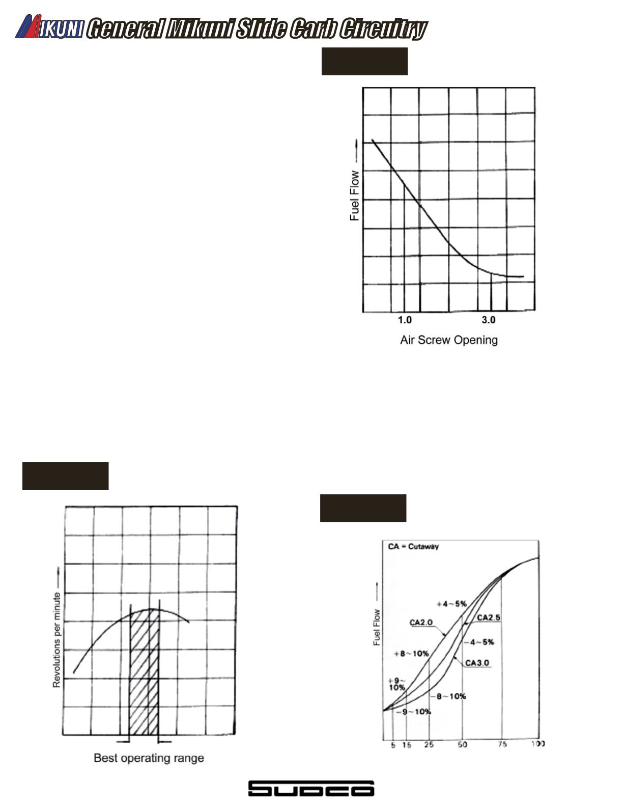
operation of the vehicle. Fig. 16 shows the fuel low curve in relation to the
opening of the air screw.
B - The Cutaway Size of the
Throttle Valve (Fig.17)
The size of the cutaway of the throttle valve affect the air-
fuel mixture ratio when the degree of the throttle valve opening is
between 1/8 and 1/2, especially in the range of the 1/8 and 1/4 opening.
As the cutaway gets larger in size, with the throttle valve opening
kept unchanged, air inlow resistance is reduced and causes the
amount of air intake to increases, resulting in a lean mixture. On the
other hand, the smaller the size of the cutaway, the richer the air-fuel
mixture will become. Interchange of the cutaway is made, when the
low speed fuel system is out of balance with the main fuel system.
General Mikuni Slide Carb Circuitry
Figure 16
Figure 15
Figure 17
540