


 545 / 612

This manual us untended as a guide for users of Mikuni
carburetors who want to learn the basic methods of tuning and
adjusting to obtain top performance and fuel economy. The arrows
that appear in the drawings in this text show direction in which air,
fuel, and air-fuel mixture lows.
Information here with in obtained from Mikuni
engineering data and manuals.
1. CARBURETOR FUNCTION
The function of a carburetor is to deliver a combustible air-fuel mixture
to the engine. However, in order to be effective, it must irst break the
fuel unto tiny particles (in the form of vapor) and then mix the fuel with
air in a proper ratio so it can burn without leaving excess fuel or a
ir.
2. AIR-FUEL MIXTURE (Fig. 1)
The mixture of the air-fuel ratio is generally expressed by its relative
weight proportion. For example, the amount of air required for
complete combustion of 1 gram of fuel under normal condition is:
Varying mixture ratios are required for the engine depending on
operating conditions. Although the required mixture ratio varies more
or less with the engine, its colling eficiency, etc., the mixture
ratio shown in ig. 1 is required for ordinary engines. In the high speed
range the ratio of about 12 to 13 grams of air for 1 gram of fuel
produces the maximum output. However, in the case of an engine with
low cooling eficiency, somewhat richer mixture (10 to 12 grams of
air against 1 gram of fuel) may be required to prevent seizure of the
engine.
3. FUNCTIONS AND CONSTRUCTION
MIKUNI SLIDE TYPE CARBURETORS
Motorcycle engines are operated under a wide range of conditions,
from idling with the throttle valve (Fig.2(1)) remaining almost closed,
to the ill load (the maximum output) with the throttle valve fully
opened. In order to meet the requirements for the proper mixture ratio
under these varying conditions, a low-speed fuel system (the pilot
system) and a main fuel system (the main system) are provided in
Mikuni Slide -type carburetors, except Mikuni TMS.
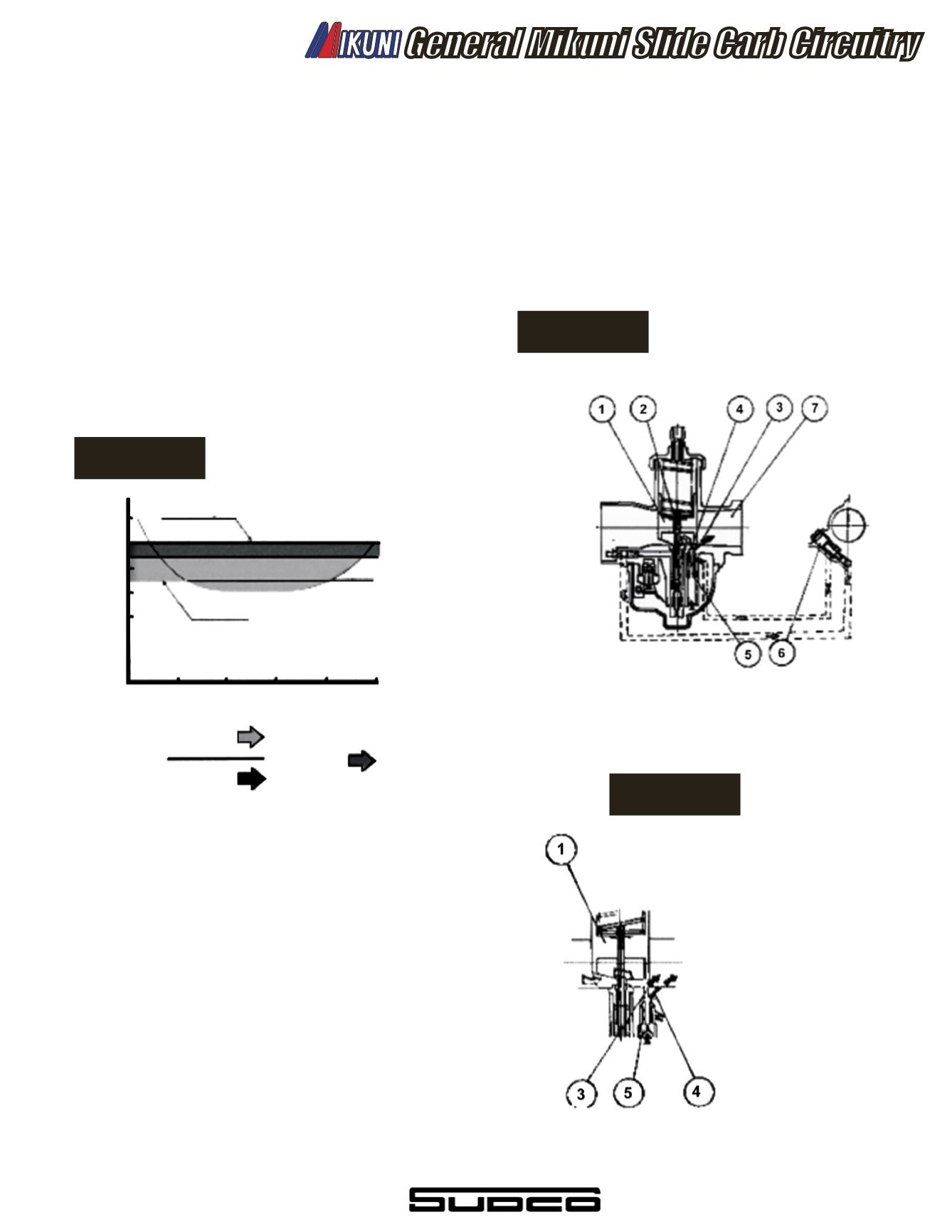
A. - The Pilot System
Low -speed fuel system (Fig. 2 and Fig.3)
Since the engine is operated with the throttle valve almost closed at
idling or in the low speed range, the velocity of air lowing through
the needle jet (2) is sloe. Consequently, a vacuum strong enough to
draw fuel from the needle jet in the main fuel system is not created. The
fuel supply during the slow speed operation is controlled by means of
the pilot outlet (3) and the bypass (4) that are situated nearest to the
engine. At idle, when the throttle valve is slightly opened, fuel
metered by the pilot jet (5) is mixed with air adjusted in a proper
amount by the air screw (6) and is broken into ine vapor particles.
The mixture is again mixed with air coming from the bypass and is
drawn into the pilot outlet to mix air lowing through the main bore (7).
The fuel mixed with air at this stage then goes to into the engine. When
the throttle valve is opened slightly during low speed operation, the pilot
outlet alone cannot supply the
required fuel and the shortage
has to be made up with fuel
injected from the bypass. The
adjustment of the mixture
ratio during this stage is
made by the pilot jet and the air
screw, as in the case of a
two-hole type fuel system
(Fig. 3). While at low speed
operation, if full throttle is
initiated a similar shortage of
fuel again has to be injected
from the bypass until enough
(vacuum) can be created to
draw fuel from the main fuel
system. There is also a one-
hole type low speed fuel sys-
tem mainly used for carburetors
having a small main bore. The
process of producing the air
fuel mixture ratio are the same
as in a two-hole type low speed
system.
General Mikuni Slide Carb Circuitry
Air-fuel mixture
Maximum power mixture ratio
Theoretical mixture ratio
Throttle valve opening (%)
20 40 60 80 100
15 gram of
1 gram of
Air
Fuel
= Mixture
RATIO
10:1
12:1
14:1
16:1
18:1
Figure 1
Figure 2
Figure 3
537