


 211 / 612

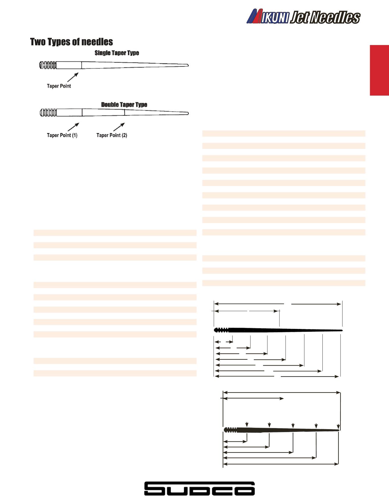
Jet Needles
The Jet Needle controls the fuel mixture in the mid-range (1/4-3/4)
throttle position. The taper of the needle determines the amount
of fuel. For example, the thinner the diameter of the needle, the more
fuel will be drawn. The thicker the diameter of the needle, the less fuel
will be drawn.
Needle Taper Diameter Dimension Chart
D-1 through D-5 indicates diameter (mm) at each point.
A
B
D-1
D-2
D-3
D-4
D-5
#4E1
50.3
28.0 2.515 2.515 2.345 2.127
1.924
#4DH7
50.3
23.0 2.518 2.518 2.386 2.098
1.790
#4J13
50.2
24.0 2.513 2.513 2.230 1.800
1.40
#4L6
50.3
24.5 2.515 2.515 2.178 1.660
1.190
#4J11
41.5
21.3 2.512 2.506 2.188 1.776
D-1 through D-6 indicates diameter (mm) at each point.
A
B
D-1
D-2
D-3
D-4
D-5
D-6
#5F3
58.0 27.4 2.519 2.519 2.419 2.135 1.863
#5EJ11
60.3 28.5 2.515 2.515 2.515 2.241 1.839 1.420
#5FL11
60.3 28.2 2.518 2.518 2.438 2.175 1.740 1.256
#5FL14
58.0 28.0 2.520 1.520 2.440 2.170 1.735
#5FL7
58.0 28.0 2.518 2.518 2.440 2.170 2.170 1.735
#5DP7
57.6 26.4 2.512 2.512 2.440 2.259 1.580
#5J6
58.0 27.5 2.518 2.518 2.340 1.890 1.450
#5L1
58.0 27.0 2.518 2.518 2.330 1.811 1.297
#5J9
58.0 27.0 2.522 2.520 1.432 1.996 1.505
D-1 through D-6 indicates diameter (mm) at each point.
A
B
C
D-1 D-2 D-3 D-4
D-5
D-6
#6F5
62.3 38.1 19.0 2.515 2.456 2.454 2.364 2.098 1.840
#6F4
62.3 32.0 19.4 2.515 2.442 2.436 2.206 1.939 1.678
#6F8
62.3 34.0 21.5 2.512 2.512 2.386 2.214 1.945 1.688
#6F16
64.6 31.2 18.4 2.520 2.404 2.400 2.201 1.941 1.679
Needle Taper Diameter Dimension Chart
(a)=Needle Length (mm)
(b)=Length between points (x) and the taper point (Y) 1=10mm
2=20mm
3=30mm
4=40mm
5=50mm
D-1, -2, -3, -4, -6 are the actual taper diameters at those given
points in millimeters
D-1 through D-6 indicates diameter (mm) at each point.
A
B
D-1
D-2
D-3
D-4
D-5
D-6
#6DH2
62.3 28.0 2.511 2.511 2.466 2.295 2.000 1.660
#6F9
62.3 28.9 2.516 2.516 2.475 2.210 1.949 1.678
#6CF1
61.5 29.5 2.512 2.512 2.429 2.240 1.974 1.710
#6FJ6
62.3 35.2 2.505 2.505 2.505 2.376 2.040 1.606
#6DH3
62.3 22.0 2.512 2.512 2.458 2.286 1.948 1.607
#6L1
62.3 37.0 2.512 2.512 2.512 2.335 1.826 1.313
#6DP17
62.3 32.1 2.518 2.518 2.518 2.372 1.834 1.141
#6N1
62.3 37.0 2.514 2.514 2.514 2.278 1.672 1.058
#6DP1
62.3 28.9 2.511 2.511 2.476 2.312 1.748 1.075
#6DH4
62.3 25.5 2.520 2.520 2.440 2.258 1.915 1.575
#6DH7
62.2 28.5 2.516 2.516 2.505 2.316 2.009 1.688
#6DH8
62.2 20.3 2.538 2.538 2.436 2.208 1.827 1.497
#6FL14
62.1 26.7 2.538 2.538 2.538 2.233 1.649 1.218
#6F15
62.2 19.8 2.535 2.538 2.461 2.208 1.979 1.649
#6DP10
62.4 26.5 2.51 2.51 2.44 2.26 1.56
0.89
#6F13
64.2 32.8 2.50 2.46 2.46 2.24 1.97
1.70
#6DL30
64.7 26.3 2.51 2.51 2.45 2.09 1.66
1.24
D-1 through D-7 indicates diameter (mm) at each point.
A
B
D-1 D-2 D-3 D-4 D-5 D-6
D-7
#7DH5
72.2 27.4 2.98 2.98 2.94 2.78 2.4 2.08 1.72
#7F7
72.3 33.1 2.99 2.99 2.99 2.80 2.54 2.28 2.02
#7F6
72.3 29.0 3.00 3.00 2.95 2.68 2.41 2.14 1.87
#7DH3
72.5 28.1 2.98 2.98 2.96 2.80 2.47 2.11 1.76
#7DH2
75.3 31.6 2.99 2.99 2.99 2.84 2.66 2.27 1.92
#4
All VM18 Carburetors,VM20
VM22, VM24
#5
VM26 - VM32 Spigot
VM28 - VM34 Flange
TM24, TM32, TM34
#6
VM30 - VM38 Spigot
#7
VM40 - VM44 Spigot
#8
HSR42, HSR45, HSR48
#9
RS34 - RS40 Smoothbore,
TM36, TM40 (HS40) Pumper Carb
#Series Type
Application
10
20
30
40
50
60
70
A
B
x
b
y
a
D-1
D-2
D-3
D-4
D-5
D-6
D-7
4
3
5
2
1
a
b
x
y
A
B
D-1
D-2
D-3
D-4
D-5
Jet Needles
V
intage
i
ntake
e
ngine
s
uspension
c
ontrol
e
lectrical
c
hemical
t
ools
W
atercraft
203
WEB:
WWW.SUDCO.COME-MAIL:
SUDCO@SUDCO.COM